
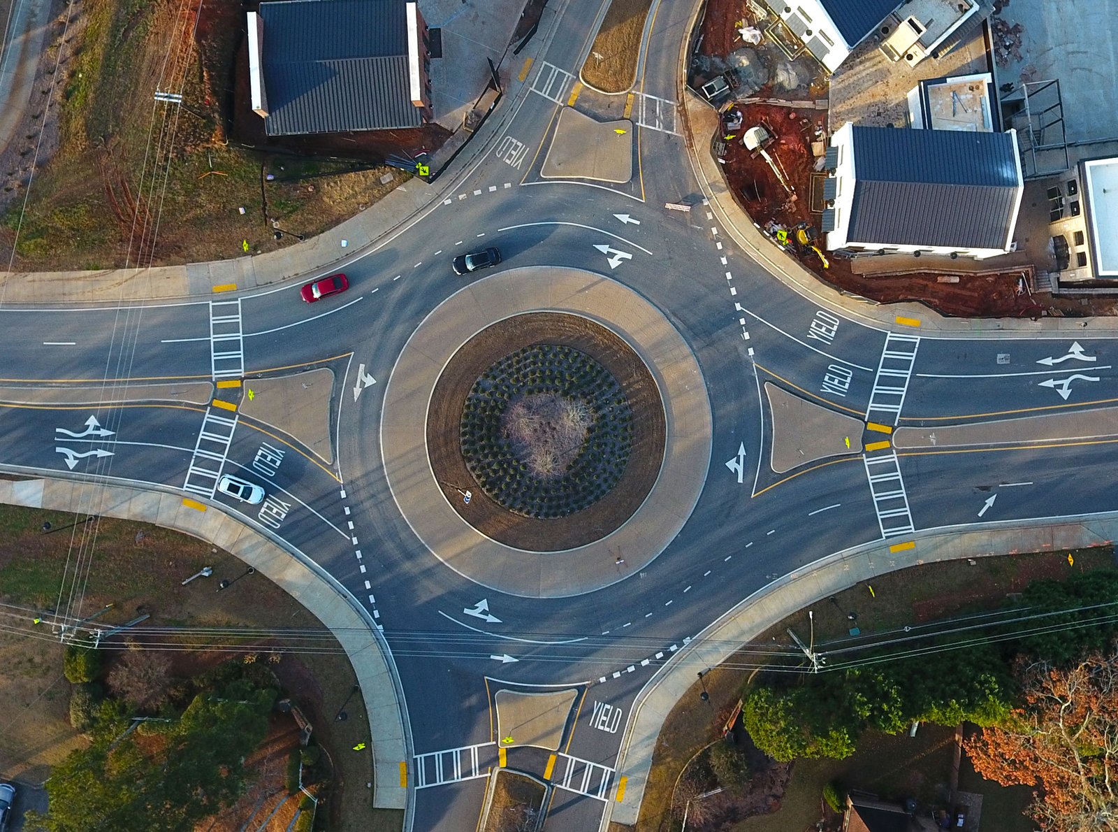
From Fastest-Path Checks to Performance-Based Geometry
Part 5 of 8 | Approximately 12 minutes
Part 4 followed the modern roundabout across the Atlantic and into American practice. Early installations demonstrated that circulating priority and speed-controlling geometry could work in the United States, while national guidance gave transportation agencies a common technical starting point.
Once roundabouts became an accepted intersection option, the design question changed. Engineers were no longer asking only whether a roundabout could work. They were asking how its size, entries, lane arrangements, signs, markings, and vehicle paths should change in response to the site.
The basic principles established in Britain remained intact. Entering traffic still yielded to circulating traffic, and the geometry still had to control speed. Later guidance made those principles more measurable and applied them to multilane intersections, rural highways, large trucks, constrained sites, and more complex traffic movements.
In This Series
- Before the Modern Roundabout
- The Modern Roundabout Is Born
- From the Laboratory to the Street
- Crossing the Atlantic
- How Roundabout Design Evolved ← You are here
- Designing for People Outside the Vehicle
- How Roundabouts Are Evaluated and Chosen
- Roundabouts Today
In This Part
- How the first national guide created a common design language
- How the fastest vehicle path became a basic speed check
- Why roundabout size became one variable instead of the design answer
- How multilane layouts exposed the path-overlap problem
- How designers accommodated trucks without widening every vehicle path
- How rural roundabouts began reducing speed before the entry
- How guidance shifted toward performance-based design
A common design language begins in 2000
The Federal Highway Administration’s 2000 guide was important partly because it organized roundabout design into a recognizable national method.
The guide described six general categories: mini-roundabouts, urban compact roundabouts, urban single-lane roundabouts, urban double-lane roundabouts, rural single-lane roundabouts, and rural double-lane roundabouts. It also defined elements such as the inscribed circle diameter, central island, circulatory roadway, entry width, splitter islands, truck apron, and fastest vehicle path.
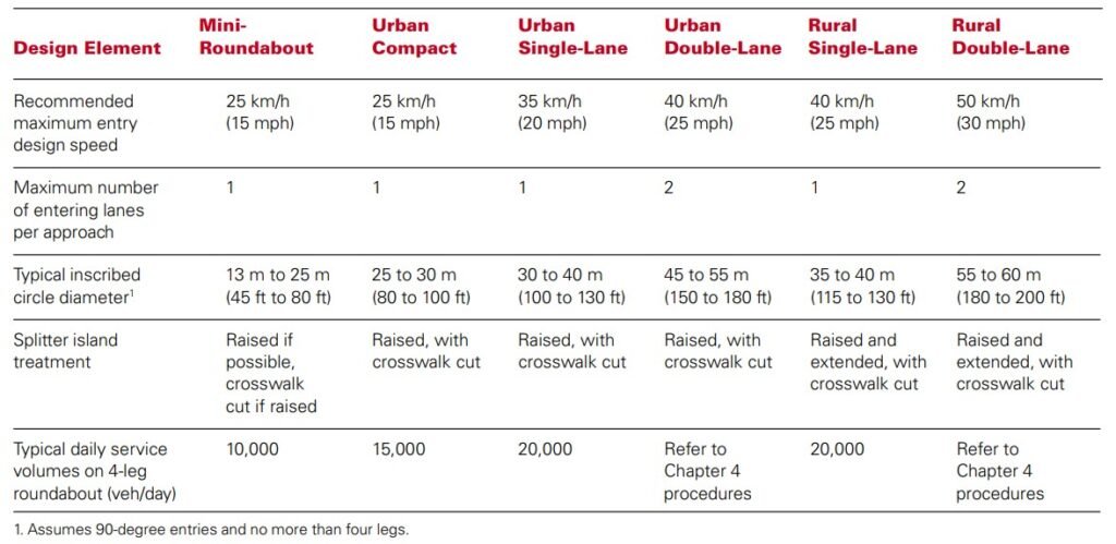
These categories helped practitioners recognize that a roundabout was not one fixed object. A compact urban roundabout and a rural multilane roundabout could follow the same operating principles while using substantially different dimensions and approach treatments.
The guide also warned against treating the categories as standard drawings. Its stated that no absolutely optimal design existed and described roundabout design as a problem of balancing traffic demand, delay, crashes, costs, and the needs of different users. The publication was guidance, not a compulsory standard or regulation.
At the time, the American body of evidence remained small. An FHWA retrospective published in 2011 states that fewer than 100 modern roundabouts existed in the United States when the original guide was published.
That situation changed quickly. NCHRP Report 572, Roundabouts in the United States, published in 2007, examined American safety and operational performance and updated design criteria using a larger domestic inventory. In 2010, NCHRP Report 672 updated the original FHWA roundabout guide based on the experience gained in the United States since 2000.
The progression from 2000 to 2010 did not replace the original geometric principles. It provided more American evidence, more detailed design checks, and a better understanding of how the elements interacted.
The fastest path turns geometry into a speed check
Roundabout speed cannot be evaluated reliably from the posted speed limit or the designer’s intention alone. The physical layout may permit a driver to take a faster path than the intended one.
The 2000 guide made the fastest vehicle path a central design check. The designer identifies the smoothest and fastest path a vehicle could follow through the entry, around the central island, and toward the exit in the absence of other traffic.
For this particular check, lane markings are not assumed to hold the driver to the exact center of a lane. The purpose is to determine what the physical geometry permits, including the path a driver might take when the intersection is empty.
The radius of that path can then be used to estimate a theoretical operating speed. A broad, gently curving path generally permits a higher speed. A tighter path requires more steering and generally produces a lower speed.
The FHWA’s 2000 Roundabouts guide also emphasizes speed consistency. A single sharp curve at the yield line is not enough if drivers can still approach the intersection at high speeds or quickly accelerate again on exit.
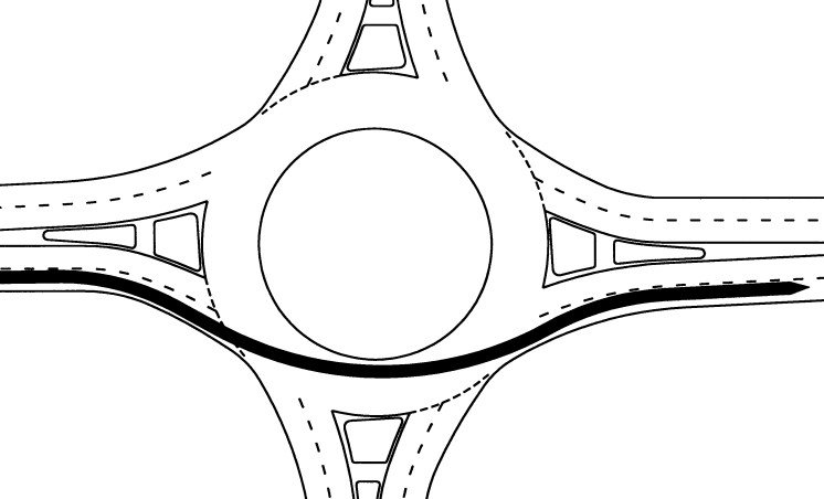
Designers therefore compare several connected paths:
- The entry path as the vehicle approaches the yield line
- The circulating path around the central island
- The exit path as the vehicle leaves the roundabout
- The paths used by right-turning and left-turning vehicles
- The corresponding paths from the other approaches
The objective here is to avoid a sequence that allows one movement to be much faster than the movement immediately before or after it. This changed roundabout design from drawing a circular island and checking whether vehicles fit around it into evaluating how a driver could actually move through the completed layout.
Size becomes one variable instead of the design answer
The inscribed circle diameter is the distance across the complete roundabout, measured between the outer edges of the circulatory roadway. It is one of the most visible dimensions on a plan, but it does not determine performance by itself.
A larger diameter can create room for a wider central island, broader splitter islands, additional lanes, and the turning space (swept path) needed for large trucks. It can also provide more flexibility when arranging several approaches around the circle. Additional space, however, can allow for faster and more direct vehicle paths if the entries and exits are not aligned carefully. A large diameter also does not automatically produce adequate deflection.
A smaller diameter may reduce land requirements and support lower speeds. But it can also make it more difficult to accommodate trucks, separate adjacent approaches, or create smooth entry and exit paths. At the same time, if the circulatory roadway is widened excessively to compensate, passenger vehicles may use that pavement to take a straighter and faster path.
The 2000 guide states that the interaction between geometric components is more important than any one component considered separately. Designers may need to test several diameters before finding a suitable combination of:
- Central island size
- Circulatory roadway width
- Entry and exit widths
- Entry and exit radii
- Approach alignment
- Splitter island length and width
- Vehicle path deflection
- Large vehicle accommodation
Splitter islands illustrate this interaction. They separate entering and exiting traffic, guide vehicles toward the correct side of the central island, discourage wrong-way movements, provide space for signs, and help establish the entry curvature. Making them larger may improve separation and make the roundabout more visible, but it can also increase the overall footprint.
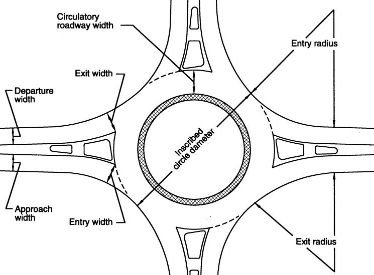
Because of these, compact designs emerged but not merely from a simple preference for smaller circles. They resulted from learning how the central island, approach alignment, splitter islands, and vehicle paths could share the work of controlling traffic.
Multilane layouts reveal the path-overlap challenge
A single-lane roundabout gives a driver one basic path through each entry. A multilane roundabout must guide two or more traffic streams through the same sequence without causing the streams to cross unintentionally.
The difficulty is that drivers do not follow pavement markings with mathematical precision. They tend to follow a smooth or natural path based on the direction in which the vehicle is already traveling. If the entry points guide a vehicle too directly toward the central island, the driver may curve outward to avoid it. If an adjacent vehicle is following its own natural path, the two paths may overlap even though the painted lanes do not.
The FHWA guide describes this as vehicle path overlap. A common example occurs when a vehicle entering from the right lane into a multilane roundabout naturally drifts toward the left lane and cuts across the path of a vehicle entering beside it.
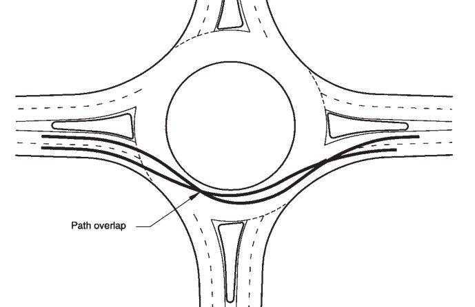
Correcting the problem is not as simple as making the entry curve tighter. A small entry radius may reduce speed, but it can also make the path change so abruptly that drivers cut across the adjacent lane. A larger radius may improve lane alignment but permit excessive speed.
The designer must balance:
- Entry speed control
- Alignment between entering and circulating lanes
- Separation between adjacent vehicle paths
- The position of the central island
- Exit alignment
- Lane use assignments
- Drivers’ ability to identify the correct lane before entering
Signs and pavement markings became increasingly important as multilane designs spread. Advance lane-use signs tell drivers which lane serves each destination. Pavement arrows reinforce that choice, and circulatory markings help drivers maintain the intended path.
Those traffic control devices cannot repair a fundamentally misaligned entry. If the geometry leads a driver across another lane, a painted line alone may not overcome the natural path. Effective multilane design therefore requires the geometry, lane assignments, signs, and markings to communicate the same movement.
Trucks are accommodated without giving every vehicle a truck-sized path
A roundabout must be able to serve the vehicles that are expected to use it. That does not mean every part of the intersection should be widened until the largest possible truck can travel through it like a passenger car.
Making every path comfortably wide for a large combination truck could allow smaller vehicles to enter and circulate too quickly. The design problem is to provide the necessary truck envelope while preserving speed-controlling paths for the vehicles that use the intersection most often.
Designers address this problem by selecting an appropriate design vehicle (e.g. a WB-67) and checking its swept path through each required movement. The swept path includes the space occupied by the vehicle body and the area tracked by its wheels as it turns.
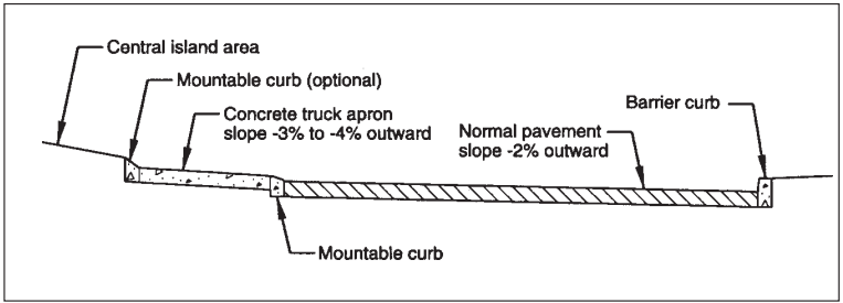
At many single-lane roundabouts, the normal circulatory roadway is designed for passenger vehicles, buses, and common trucks. A larger truck may be allowed to track onto a mountable truck apron around the central island.
The apron creates two overlapping paths:
- Passenger vehicles remain on the lower circulatory roadway and follow a tighter, speed-controlling path.
- Large trucks can use part of the raised or differently textured apron when their rear wheels need additional turning space.
This allows the central island to remain large enough to influence passenger-car paths without preventing necessary truck movements.
A truck apron is not a complete solution by itself. Its curb height, slope, surface, drainage, visibility, and relationship to the truck’s ground clearance all affect whether it can be used safely. Buses and frequent trucks may also require a path that does not depend heavily on mounting the apron.
The larger lesson is that vehicle accommodation became movement-specific. Designers began checking which large vehicles were expected, how frequently they would appear, which turns they needed to make, and whether a different route or occasional encroachment was acceptable.
Rural approaches move speed control upstream
An urban driver may approach a roundabout from a street that is already operating at a relatively low speed. A rural driver may approach from a long, straight highway at a much higher speed.
If all the required deceleration occurs immediately before the yield line, the driver may arrive too quickly, brake sharply, or fail to recognize the intersection in time. The final entry curve cannot carry the entire responsibility for reducing speed.
The FHWA guide recommended moving the beginning of the speed transition farther upstream. Treatments included longer splitter islands, visible changes in the roadway cross section, signs and marking, and a sequence of progressively sharper approach curves.
The concept is similar to the connected movement paths inside the roundabout. Each stage prepares the driver for the next:
- Advance signs identify the approaching intersection.
- Changes in alignment and the roadway environment to attract attention.
- The splitter island separates opposing traffic and begins directing the vehicle toward the entry.
- Successive curves reduce speed in manageable stages.
- The final entry geometry establishes the low-speed yielding movement.
The guide specifically illustrates the use of successive curves on high-speed approaches. The curves become sharper as the driver approaches the roundabout instead of requiring one abrupt change at the end.
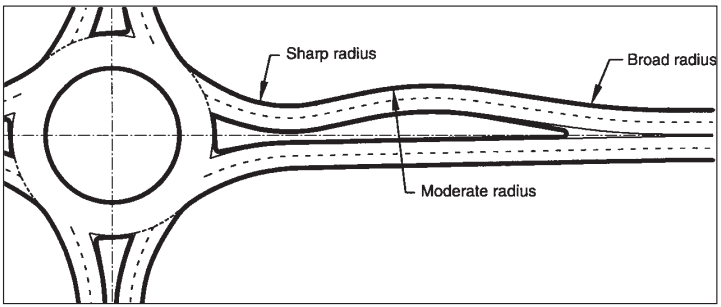
Central-island landscaping, lighting, advisory-speed signs, and other visual treatments can reinforce the transition. They still must preserve the sight distance needed for drivers to see the yield line, circulating vehicles, and other roadway users.
The rural design problem therefore expanded the meaning of roundabout geometry. The design did not begin at the circular roadway, but rather at the point where an approaching driver first needed to recognize the upcoming roundabout intersection and start reducing speed.
Guidance becomes performance based
The early American guides already described roundabout design as iterative. The 2000 guide stated that an optimal layout was rarely produced on the first attempt and that small geometric modifications could create substantial changes in performance.
Later guidance made that process more explicit. The 2023 Guide for Roundabouts, published as NCHRP Research Report 1043, incorporates the lessons gained from the larger number and wider variety of roundabouts constructed in the US.
The way this guide is organized reflects the change in approach. The guide includes a chapter on performance-based planning and design, separate safety and operational analyses, a geometric design process with performance checks, detailed horizontal and vertical design, traffic control devices, and final construction and maintenance considerations.
Under this approach, the designer does not begin with a standard diameter and attempt to make every requirement fit inside it. The process is closer to the following:
- Identify the site context, users, vehicles, and intended outcomes.
- Determine the traffic movements and lane requirements.
- Develop an initial geometric concept.
- Draw and evaluate the fastest paths.
- Check large-vehicle swept paths.
- Evaluate lane alignment, speed consistency, visibility, and traffic control.
- Adjust the geometry and repeat the checks.
- Document how the completed design meets the project’s objectives.
A performance-based process does not mean that dimensions, standards, or established design principles are optional. It means that simply meeting the required dimensions is not considered proof that the intersection will function as intended.
The signs, markings, curbs, islands, and approach alignments are evaluated as parts of the same system. A change that improves one movement may create a problem for another, so the design is refined until its components work together.
That is the central change in how roundabout design evolved. The modern roundabout became an intersection form whose geometry could be adjusted and tested against the performance required at a particular site, rather than a collection of increasingly complicated standard plans.
The next design challenge extended beyond motor vehicles. Lower speeds and shorter crossings created opportunities for pedestrians and bicyclists, but roundabouts also introduced questions about crossing location, driver yielding, bicycle routing, and navigation for people with vision disabilities.
How designers began addressing those users is covered in Part 6.
← Previous: Part 4, Crossing the Atlantic
Next: Part 6, Designing for People Outside the Vehicle →
Leave a Reply