
Part 3 of 5 | Approximately 8 minutes
Early automatic signals followed predetermined timing plans whether traffic was present or not. This part examines how detection allowed signals to respond to vehicles and pedestrians, and how electronic controllers greatly expanded what signals could do. It also follows the development of standardized and open controller architectures and the transition from isolated field equipment to centrally managed networks. These advances made signal operation more flexible, but they also created new responsibilities for detection, communications, software, maintenance, and system management.
In This Series
- Before the Modern Traffic Signal
- From Isolated Signals to a National System
- The Signal Becomes Responsive and Networked← You are here
- Expanding Whom and What the Signal Serves
- The Modern Signal and Its Future
In This Part
- How Pretimed Signals Worked
- Detection Makes the Signal Responsive
- Electronic Controllers and Open Architecture
- Central Computers and the Networked Signal
How Pretimed Signals Worked
Early automatic signals generally followed predetermined schedules. A pretimed, or fixed-time, controller assigns a set cycle length, sequence, and duration to the available movements (phases). The signal repeats that plan regardless of whether a vehicle or pedestrian is actually present. Different plans may be scheduled by time of day, but each active plan is still predetermined.
Pretimed operation is not inherently obsolete. It can work well where demand is predictable, intersections are closely spaced, pedestrian activity is consistent, or reliable detection is unavailable. Its weakness is that it cannot directly respond to short-term variation. A side street can receive green with no vehicle present, or a queue can outlast its allotted green even when another movement has little demand. FHWA distinguishes pretimed control from actuated control on this basis. (FHWA Signalized Intersections: Informational Guide, Chapter 4)
The electromechanical controller made repetitive automatic operation possible using timers, relays, cams, dials, and related hardware. The signal plan was embodied physically in the machinery. These systems could be dependable, but changing their operation required physical adjustment and their capabilities were limited compared with later electronic controllers.
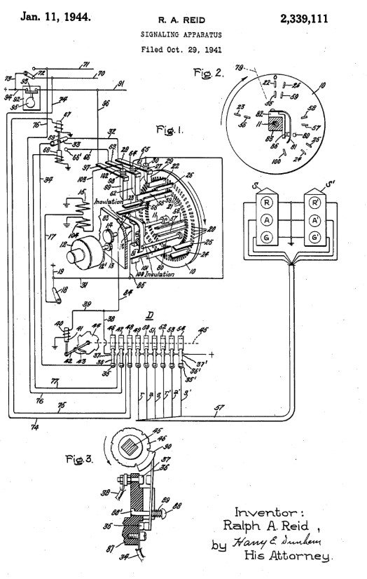
The important historical shift involved more than replacing a police officer with a machine. Traffic control moved from real-time decisions made by an officer to a predetermined timing plan developed by engineers. This made signal operation more consistent and easier to implement at many intersections, but it also required agencies to regularly review and update the timing plan as traffic conditions changed.
Detection Makes the Signal Responsive
Vehicle-actuated control added a feedback loop. Instead of serving every movement solely because the clock reached a certain point, the controller could receive a call (which is an actuation or a signal from the detector) indicating that a vehicle, pedestrian, or other user was waiting. Depending on the configured logic, the call could cause a phase to be served, extend a green interval, or influence when the green should terminate.
Inductive-loop detectors became one of the principal vehicle-detection technologies. A loop of wire embedded in the pavement changes its electrical characteristics when a vehicle enters the detection zone. The detector electronics translate that change into a call to the controller. In 1981, NEMA (National Electrical Manufacturers Association) established standards for loop detectors to improve interchangeability and ensure consistent performance. Later revisions added delay and extension timing functions. (FHWA Traffic Detector Handbook)
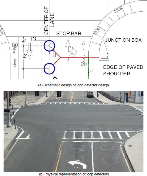
Other detector families developed to avoid pavement cuts or provide different forms of information. FHWA’s detector handbook discusses video image processing, microwave radar, infrared, acoustic, magnetic, and other technologies. Modern agencies may use combinations of detection to identify presence, count vehicles, estimate speed, classify users, or monitor queues. The technology name alone does not guarantee performance. Detection-zone design, camera occlusion, lighting, weather, pavement condition, communications, maintenance, and controller programming determine whether the detector actually supports the intended operation.
Actuation improved efficiency, especially when demand varied, but it also made the system dependent on reliable detection. A failed detector can hold a call continuously, omit a needed call, terminate a phase incorrectly, or cause the controller to revert to less efficient operation. FHWA notes that actuation can reduce frustration and better serve minor approaches, but it requires proper detector operation and increases maintenance needs. (FHWA Signalized Intersections: Informational Guide, Second Edition)
Pedestrian push buttons are also detectors. They do not usually cause an immediate WALK indication. They register a request that the controller serves at an appropriate point in the sequence, subject to minimum vehicle and pedestrian timing, coordination, and other constraints. This distinction between detection and immediate service remains important in public understanding of signals.
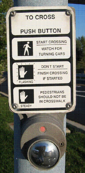
This operating logic explains why pedestrian push buttons are sometimes disparagingly called “beg buttons.” The term reflects frustration that pedestrians may have to make an explicit request for service, whereas motorists often receive a green indication automatically or place a request passively through vehicle detectors. Technically, however, the push button is simply a pedestrian detector. The concern behind the nickname is not the button itself, but signal operations that make pedestrian service conditional, infrequent, or excessively delayed.
Electronic Controllers and Open Architecture
As signal logic became more sophisticated, controllers moved from electromechanical timing to solid-state electronics and programmable microprocessors. This transition made it possible to store multiple timing plans, operate complex phasing, process many detector inputs, communicate with central systems, record events, and support priority or preemption functions.
The American traffic-signal controller environment developed through several major equipment families. NEMA standards focused on standardizing controller functions and electrical interfaces so that agencies could use compatible equipment from different manufacturers without redesigning the entire signal cabinet. California and New York developed the Type 170 specification in response to similar concerns about equipment compatibility, but followed a different approach. Rather than primarily standardizing functions, the Type 170 established a common hardware platform on which agencies could run separately developed traffic-control software.
The later Model 2070 and Advanced Transportation Controller standards extended this concept by creating more open and flexible computing platforms. These controllers were designed to support signal control and other transportation applications on field-hardened, general-purpose computers operating in real time. Together, these developments gradually expanded the meaning of interchangeability from simply replacing one controller with another to allowing greater flexibility in selecting hardware, software, and system components. Complete interchangeability still depends on compatibility among the controller, cabinet, software, and communications system (FHWA Traffic Detector Handbook; ITE Advanced Transportation Controller standards).
The controller cabinet also contains more than just the controller. Load switches operate field indications. Monitoring equipment checks for conflicting or unsafe electrical outputs and can place the intersection into a fail-safe condition (flashing red for all) if an abnormal state is detected. Detection electronics, power distribution, communications devices, battery backup equipment, and other components support the operation. The modern signal is therefore a safety-related control system, not merely a set of lamps connected to a timer.

Open architecture and standardized interfaces were intended to reduce dependence on incompatible proprietary components and to allow agencies to purchase hardware and software from multiple sources. In practice, interoperability still depends on the standards implemented, agency specifications, software, firmware, testing, and integration. A standard-compatible label does not remove the need for systems engineering or acceptance testing.
Central Computers and the Networked Signal
Coordination initially relied on mechanical or electrical timing relationships. Central computing expanded the scale and speed of network management. In the early 1970s, FHWA’s Urban Traffic Control System work used central computers and network models to test signal-control strategies in Washington, D.C. (FHWA CORSIM history)
The major change was the ability to supervise many intersections as one operational system. Central software could select timing plans, monitor controller status, receive detector data, identify some failures, and allow an operator to change settings without visiting every cabinet. Communications moved through leased lines, twisted-pair cable, fiber, radio, cellular service, and other media as technologies changed.
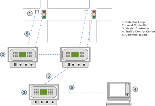
Network control also introduced organizational responsibilities. An agency needed communications maintenance, controller databases, timing records, software support, access controls, trained staff, and procedures for failures or upgrades. The signal system became part of transportation systems management and operations (TSMO) rather than only a collection of construction assets.
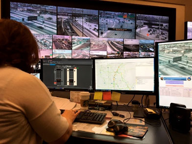
FHWA’s current Traffic Signal Program Handbook reflects this broader view. Effective signal management includes planning, design, operations, maintenance, objectives, performance measures, workforce capability, and lifecycle management. A signal can display red, yellow, and green and still provide poor service if detection is failed, timing is obsolete, communications are unreliable, or staffing is inadequate. (FHWA Traffic Signal Program Management)
By this stage, traffic signals had evolved from fixed mechanical devices into responsive and centrally managed systems. The next stage expanded both their functions and the users they were designed to serve. Part 4 examines pedestrian and bicycle accommodations, more precise signal displays, LED technology, and priority and preemption.
← Previous: Part 2, From Isolated Signals to a National System
Leave a Reply